Learn Electronics/Capacitors
Materials[edit | edit source]
See also Dielectrics
Charging and Discharging[edit | edit source]
Charging[edit | edit source]
- Capacitors can be thought of as temporary sources of voltage. Assume that a capacitor is rated at 10 volts, then, to charge it, any voltage up to 10 V can be supplied to its terminals, possibly directly, or via a series resistance. Many capacitors require proper polarity (direction of applied voltage), otherwise damage could be the result. Capacitors need not be, but can be fully charged.
- At the moment of first connecting the voltage source to the capacitor a large current flows into the capacitor, and, if desired, that amount of current can be limited by a series resistor. The voltage source usually has an internal resistance in addition, but that resistance may be neglected in some calculations. As the capacitor charges, the voltage at its terminals increases, and because it opposes the applied voltage therefore the charging current decreases until it stops. The capacitor is then fully charged, the voltage at its terminals then being equal to the supplied voltage.
- Usually, if left alone for some time, a charged capacitor loses its charge slowly. Note that a voltmeter connected across the terminals of a capacitor represents a "load" and in some calculations may not be neglected.
- If AC is connected to a capacitor, then the capacitor will charge and discharge during each cycle, with an alternating current flowing that can be computed from moment to moment by assuming that the AC voltage is actually a changing DC voltage at each moment, and carefully noting whether the existing voltage across the terminals of the partly charged capacitor adds to, or subtracts from, the applied AC voltage at that moment.
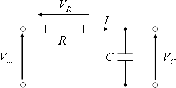
- There are three voltages in the circuit. 1) Vin the supply voltage, 2) VR the "voltage drop", which is lost across the resistor and is proportional to the current flowing, and 3) VC the voltage across the terminals of the capacitor/condenser.
Discharging[edit | edit source]
Capacitors when charged are equivalent to a DC voltage source, and the circuit components connected across the capacitor's terminals determine the magnitude of the discharge current. Any such current reduces the amount of charge, and therefore also reduces the voltage across the terminals of the capacitor.
more...[edit | edit source]
Capacitor Circuit Diagram[edit | edit source]
Information[edit | edit source]
The capacitor is another important basic circuit component. They are used as a means of storing energy. They consist of two conducting plates separated by an insulator. Charge will not flow directly through a capacitor. Instead, when a voltage is applied, charge will accumulate on both plates. The accumulation of charges creates an electric field between the two plates, which is the means of energy storage. Eventually, the plates will 'fill up' with charges and no more will accumulate. At this point, the capacitor has an amount of energy stored that is determined by its size and voltage applied across it. The energy can then be discharged into an electrical load via some manner of switch. The size of a capacitor is determined by several factors: physical size, insulator material used, closeness of the plates, etc. Voltage rating is determined similarly. Capacitor size is measured in farads. Typical capacitor sizes used are in the microfarad range, although the lower bound for typical uses can be as low as picofarads, and as high as millifarads.
At low frequencies, capacitors are fairly uninteresting. After they fill up with charge, nothing happens. Thus, at low frequencies (also, after a long time), they act as an open circuit. However, at shorter time spans (higher frequencies), they show more useful behaviors. They can be combined with a resistor in parallel to control the flow of charge into them, which allows them to charge and discharge at a certain rate. These properties are used extensively in timing circuits, such as a 555 timer square wave generator. Capacitors are also used for filtering. By pairing them with resistors in series, capacitors can reduce the amplitude of sin waves. The reduction in amplitude is a function of frequency. By tuning the values of the resistor and capacitor, the frequencies affected and magnitude of reduction can be altered.
See also[edit | edit source]
Resistance-Capacitor-Inductance circuits
Previous chapter Resistors | Next chapter: Inductors | Go back to Index
